
Define variables with the given specifications of the filter. The graph is unable to plot below 1Hz at the moment.

Zener Diodes Connected In Series As Well As Producing A Single Stabilised Voltage Output Zener Diodes Can Also Be Co Diode Electronic Circuit Projects Diodes
The frequency response function or transfer function of the RC low pass filter is given by V o u t V i n A 1 j ω T A 1 j ω ω 0 A 1 ω ω 0 2 tan 1 ω ω 0 Where T Time constant of the circuit 1 ω 0 R C.

. Note that once again it is possible to define a cutoff frequency at ω 0 1RC in the same way as was done for the low-pass filter. Practically such kind of frequency response is not possible. This means that the resistance that it offers to a.
This is the common example of low pass filter. The response in both the high and low frequency regions are straight lines. The output frequency is rounded to the second decimal place.
The frequencies of these guitar chords are filtered based on the highlow pass filter above. Please notify the admin if there are any. For a basement system I bought a little subwoofer with a built-in high pass filter that would allow me to fill in the bass where my bookshelf speakers struggle.
The series RC high pass filter. As we have already studied low pass filter which blocks low frequency passing through it and only allows higher frequencies to the output but on the other hand high pass filter is opposite to that of low pass filter. When 0 is placed inside we get edges which gives us a sketched image.
An inductor is a reactive device. On a high pass filter values lower than the frequency cutoff f_c point will be filtered out - you will see the magnitude of their waveforms decrease as they pass the frequency cutoff. The main difference between a low pass and high pass filter is that the low pass filter circuit passes frequencies lower than the cut off frequency while the high pass filter passes frequencies higher than the cut off frequency.
The frequency response graph of an ideal filter looks something like this. When one is placed inside and the zero is placed outside we got a blurred image. In addition it graphs the bode plot for magnitude in decibels and the phase in radians.
Common high pass filter slopes are 6dB 12dB 18dB and 24dB per octave. This tool calculates the crossover frequency for a RC high pass filter. In a low pass filter frequency values higher than the frequency cutoff f_c point will be filtered out.
When an resistor is placed in series with the power source of the circuit and an inductor is placed in parallel to that same power source as shown in the diagram circuit above this type of circuit forms a high pass filter. The log of the frequency is graphed on the x-axis and the gain on the y-axis. LR High Pass Filter Build a series circuit with a 1KΩ resistor and an 25mH inductor and probe the frequency response by observing the voltage across the inductor.
And the phase shift. A high-pass filter is usually modeled as a linear time-invariant system. A high-pass filter HPF is an electronic filter that passes signals with a frequency higher than a certain cutoff frequency and attenuates signals with frequencies lower than the cutoff frequency.
From scipy import signal. All frequencies above the cutoff frequency remain at their original amplitude. Imagine a high pass filter with the cutoff frequency set to 400Hz and a slope of 12dB per octave.
It is sometimes called a low-cut filter or bass-cut filter in the. ω 0 Cut off frequency. If we consider the frequency response of the circuit it is found that this will pass signals with high frequencies.
Import numpy as np. All high pass filter graph wholesalers high pass filter graph manufacturers come from members. A CR circuit is shown below.
If we recall from section 3 the impedance of the capacitor is. We doesnt provide high pass filter graph products or service please contact them directly and verify their companies info carefully. Figure 4 Frequency response of an RC high-pass filter.
The subwoofers speaker-level high pass filter is specified at. A high pass filter is a circuit that allows the higher frequency above cutoff frequency and attenuates all the frequency below the cutoff frequency ƒc. It forms a high pass filter because of the reactive properties of an inductor.
The following chart shows the attenuation of each frequency relative to the cutoff frequency. A Constant and. The amount of attenuation for each frequency depends on the filter design.
Importing all the necessary libraries. My bookshelf speakers are specified at. Observe the chart below.
An ideal high pass filter blocks signal completely having frequency lower than a pre-selected frequency known as cutoff frequency and allow any frequency high than cutoff frequency without any attenuation. The following high pass filter response graph shows the waveform image indicating how all frequencies below a selected cut-off threshold are attenuated or blocked gradually as frequency decreases. Now as we increase the size of 1 blurring would be increased and the edge content would be reduced.
The following graph shows the gain plotted against the frequency. This is a common example of high pass filter. RC High Pass Filter - Frequency and Bode Plot Calculator.
Low Pass Filter Bode Plot. Frequency response 80Hz to 20KHz 3dB. Import matplotlibpyplot as plt.
The following two images are configured as standard high-pass filter circuits where the first one is designed to work with a dual supply whereas. Both low pass and high pass filters use a resistor and a capacitor but the orientation in each is reversed. Amplitude and phase response curves for the high-pass filter are shown in Figure 4.
The following is a graph of the ideal magnitude response of a high pass filter. A high pass filter is a frequency filter that allows passes frequency above a certain cutoff frequency and disallows stops the frequencies below that cutoff frequency. These plots have been normalized to have the filter cutoff frequency ω 0 1 rads.

Pin Na Nastence Loudspeaker

Sawtooth Wave Generator Circuit Using Ujt Eleccircuit Com Basic Electronic Circuits Electronic Circuit Projects Circuit Projects

Pin On Low Pass Filters
Medical Education Chart Biology Urinary Excretory System Medical Education Study Biology

Pin On Phonics Reading

Sanwa Cd732 Digital Multimeter Meterbdツ Multimeter Sanwa Digital

Got 890 Mrks Computer Science Economics Science

The Classes And Classification Of Amplifiers And Its Applications Electronics Basics Electronic Circuit Projects Amplifier

Ten Watt High Quality Stereophonic Amplifier In 2022 Valve Amplifier Amplifier Watt

This Is A Great Eq Frequency Chart That You Can Use When Mastering With This Charts You Can Easily Point Out The Frequencies Of The Instrument That You Want To

Deepmind S Meta Learning Sparse Compression Networks Set New Sota On Diverse Modality Data Compression Syn In 2022 Meta Learning Learning Methods Learning Techniques

Led Graph Circuits Nuts Volts Magazine Graphing Circuit Electronics Projects

Deepmind S Meta Learning Sparse Compression Networks Set New Sota On Diverse Modality Data Compression Syn In 2022 Meta Learning Learning Methods Learning Techniques

What Is A Low Shelf And High Shelf Filter In Parametric Equalization Low Shelves Filters Parametric

Flux Mini Free Modulation Effect Plugin Audio Flux Ipad Os

What Is A Low Shelf And High Shelf Filter In Parametric Equalization Low Shelves Filters Parametric
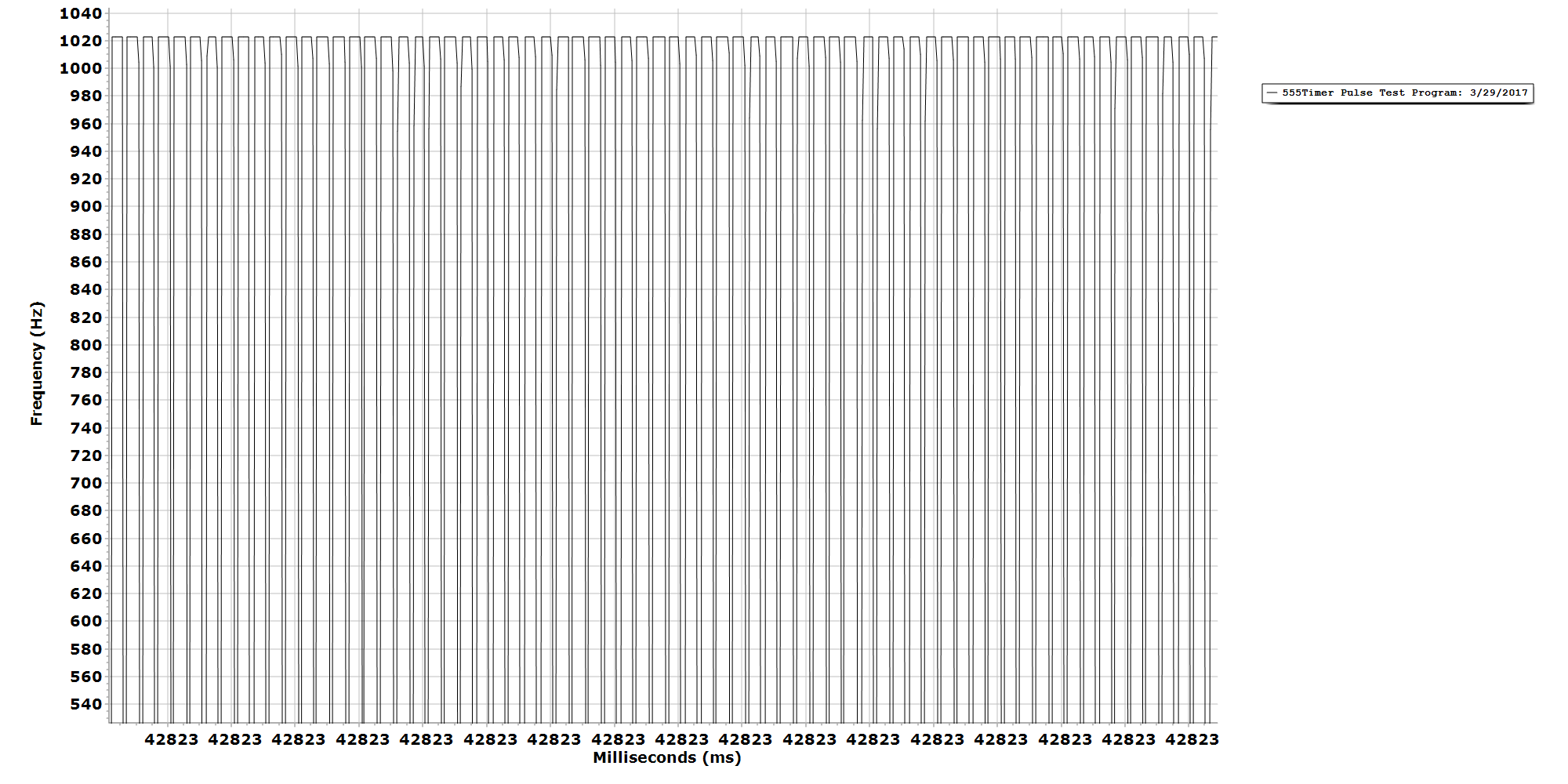
Chart Diagram Line Chart

Gtr3 Stomps Plugins Waves Plugins Guitar Effects Pedals Music Mixing

Led Graph Circuits Nuts Volts Magazine Graphing Circuit Electronics Projects
- hong leong islamic bank annual report
- contoh motto motivasi pendidikan
- fungsi lukisan batik
- mimpi ikan cina
- telur hancur dalam bahasa inggris
- lampu ruang tamu kayu
- big stage 2019 online
- tgv sunway velocity indulge contact number
- gambar rumah di kampung
- tempat berbuka puasa di kuala lumpur
- ubi bit putih
- harga kain lap mobil
- lee min ho y suzy
- tokoh perdana menteri malaysia
- telefon murah tapi canggih
- bacaan ipu hari ini
- defence services sdn bhd
- undefined
- high pass filter graph
- kata kata selamat hari minggu buat sahabat


